VISUINO Remote Control Module + Stepper Motor + OLED Lcd + Drv8825 Drive
2026-04-16 | By Ron Cutts
License: GNU Lesser General Public License Displays Microcontrollers Motors Arduino ESP32
In this tutorial, we will use an OLED LCD, a stepper motor, a remote control, a stepper driver (DRV8825), and Visuino to make the stepper motor rotate when we press a button on our remote control.
Watch a demonstration video.
What You Will Need
Arduino Mega (can be any other Arduino)
Breadboard (or breadboard shield)
Red LED (or any other color)
Remote Control 315MHz 4 Channel Wireless
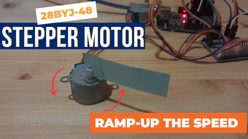
Stepper motor 28BYJ48 (can be any other stepper; just make sure that you know how to wire it to the controller)
Visuino program: Download Visuino


The Circuit
The connections are pretty easy; see the above image with the breadboard circuit schematic.
Connect the breadboard positive pin to the Arduino 5V pin and connect the breadboard negative pin to the Arduino GND pin.
Connect the positive pin of the LED to the resistor and the other to the GND pin on the breadboard.
Connect the resistor pin to the breadboard positive pin and the other resistor pin to the button pin.
Connect the OLED LCD positive pin to the breadboard positive pin and the OLED LCD negative (GND) pin to the breadboard negative pin.
Connect OLED LCD SCL pin to Arduino SCL pin
Connect the remote control + pin to the breadboard positive pin
Connect the remote control GND pin to the breadboard negative pin
Connect the remote control D3 pin to Arduino pin(3)
Connect the remote control D2 pin to Arduino pin(4)
Connect the DRV8825 RESET and SLEEP pins to the breadboard positive pin
Connect the DRV8825 GND pin to breadboard negative pin
Connect the DRV8825 DIR pin to Arduino pin (5)
Connect the DRV8825 STEP pin to Arduino pin (6)
Connect the power supply for the motor to the DRV8825 VMOT and GND
Connect the Capacitor across VMOT and GND
Connect the stepper motor as shown in the picture.
(Note that this motor is UNIPOLAR, but the driver is used for BIPOLAR motors, so we will wire this motor as if it were BIPOLAR.) This means that we will leave one wire unconnected.
**If the motor is humming and not moving when you run the circuit, it means that the wires of the motor are not connected correctly
**To check what wires are A1, A2, or B1, B2 on a motor, use a multimeter (beep function) and connect wires to it; if it beeps, it means you have found the right pair


Start Visuino, and select the Arduino MEGA board type.
To start programming the Arduino, you will need to have the Arduino IDE installed from here: http://www.arduino.cc/.
Please be aware that there are some critical bugs in Arduino IDE 1.6.6. Make sure that you install 1.6.7 or higher; otherwise, this will not work! If you have not done so, follow the steps to set up the Arduino IDE to program the ESP8266!
The Visuino: https://www.visuino.eu also needs to be installed.
Start Visuino as shown in the first picture. Click on the "Tools" button on the Arduino component (Picture 1) in Visuino
When the dialog appears, select "Arduino MEGA 2560" as shown in Picture 2


Add and Connect Pulse Generator, Logic Gates,Delay, and OLED Component
Add Pulse Generator, set frequency to 100 (it will auto-change to 1E2) see pic2
Add two AND Logic gates
Add two Delay components and set interval to 50
Add OLED display component
Double-click the OLED component ad in the dialog (right)
select "Fill screen" drag it to the left side under properties, set color to tmcBlack
select "Draw Bitmap" drag it to the left side under properties "Bitmap", load the desired bitmap (like an arrow pointing right), under properties "X" set it to 40
select "Draw Bitmap" drag it to the left side under properties "Bitmap", load the desired bitmap (like an arrow pointing left), under properties "X" set it to 40


In Visuino: Connecting Components
Connect Pulse Generator pin Out to logic gate1 component pin [1]
Connect Pulse Generator pin Out to logic gate2 component pin [1]
Connect Arduino Digital Out pin [3] to logic gate1 component pin [0]
Connect Arduino Digital Out pin [4] to logic gate2 component pin [0]
Connect logic gate1 component pin [Out] to Arduino Digital pin [5] and pin [6]
Connect logic gate2 component pin [Out] to Arduino Digital pin [7]
Connect Display OLED Pin [Out] to Arduino Pin I2C [In]
Connect Display OLED - Elements Fill Screen1 Pin [Clock] to Arduino Digital Out Pin [3]
Connect Display OLED - Elements Draw Bitmap1 Pin [Clock] to Delay1 Pin [Out]
Connect Display OLED - Elements Draw Bitmap2 Pin [Clock] to Delay2 Pin [Out]
Connect Display OLED - Pin [In] to Arduino Serial out pin [0]
Connect Delay1 component pin [start] to Arduino Digital out pin [3]
Connect Delay2 component pin [start] to Arduino Digital out pin [4]
Generate, Compile, and Upload the Arduino Code
In Visuino, at the bottom, click on the "Build" tab, make sure the correct port is selected, then click on the "Compile/Build and Upload" button.

Play
If you power the Arduino Mega module, the OLED LCD will start showing an arrow. Once you press a button on the remote, the stepper will start to rotate in the desired direction.
Congratulations! You have completed your Stepper motor project with Visuino. Also attached is the Visuino project that I created for this. You can download and open it in Visuino: https://www.visuino.eu